


Volume flow controller
VRM 300
variable, electronically/pneumatically regulating - circular
- For application in complex piping systems for the controlling the amount of air distribution
- Pressure measurement via measuring nozzle integrated in the housing
- Integrated shut-off damper, airtight according to DIN EN 1751 Class 4
- All components connected and wired at the factory
- Volume flows and controller set or programmed at the factory
- With lip sealing
- Laser-welded housing
- Special execution: ATEX, painted, stainless steel or with insulation shell or two-sided board or flat flange available at a surcharge
Functioning
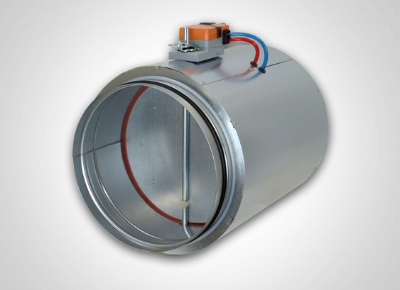
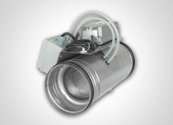
The electronic and pneumatic volume flow controller we have developed represents a logical extension of our product range. The volume flow controller consists of a regulating flap, which can also serve simultaneously as a shut-off damper, and a nozzle for volume flow measurement incorporated in the housing. The nozzle is designed according to the standards DIN EN ISO 5167, so that the differential pressure at the nozzle represents a definite physical quantity, on the basis of which the volume flow can be calculated directly. As a result, it has been possible to dispense with the empirical determination and arrangement of measurement holes for velocity measurement. This differential pressure is transmitted to the measurement sensor of the controller, which adjusts the regulating flap or shut-off damper according to the corresponding guidelines via a servomotor. Depending on the make of the controller, the volume flow controller can perform different functions, e.g.: using a command signal to adjust volume flow on a continuous scale between set minimum and maximum values, shutting off, or implementing a “master-slave” servo-control.
Design
The pipe bodies are manufactured from galvanised sheet steel and are finished as laser-welded pipes. In its endeavour to raise quality levels and increase the airtightness of welded pipe bodies, Aerotechnik Siegwart was the first company to use laser welding on galvanised sheet steel in serial production. Laser welding has the advantage that the welding seam is airtight over the entire length of the seam and there is no burning of the peripheral areas of the welding seam. As a result, neither subsequent application of sealing compound nor corrosion protection is required.
In addition, the laser-welded seam forms a smooth surface with no overlap, which is an important condition for an airtight connection between the push-fit end and the pipe. The tube bodies are manufactured with lip sealing. High rigidity is achieved via an all-round stop and stiffening bead. The lip sealing makes additional sealing of the connection point unnecessary, which is a great advantage precisely in the case of ceiling, wall and corner oriented installations. This also results in a considerable reduction of installation time wherever the device may be connected.
Likewise, no unsightly sealing tape is necessary when it is installed in a visible area. The dimensions of the tube bodies comply with the standard for circular piping components. The diameters are graded in the series R20. As a result, no further size reductions, which could interfere with the piping scheme, are required. The regulating flap, which serves simultaneously as a shut-off damper, is designed as a double disc made from galvanised sheet steel. A continuous sealing disc made of non-ageing and hygienic silicone rubber, or alternatively of EPDM, is located between the sheet steel discs. The shaft runs on floating bearings and is protected against axial displacement by retaining rings. Owing to the design of the bearings, only low torques are required for operation of the regulating flap.
Moreover, the axial bearings provide the controller with additional dimensional stability.
The nozzle for volume flow measurement is pressed from galvanised sheet steel. Drill holes are provided in the nozzle for recording pressure.
The pressure recording points on the overpressure and negative pressure sides, with four respectively distributed around the circumference, are each connected via a closed circuit, providing a mean value and ensuring that a sufficiently accurate velocity is measured even with disturbed velocity profiles.
The surface ratio of the nozzle for volume flow measurement (the ratio of the free nozzle cross-section to the pipe cross-section) is designed in such a way that the flow velocity in the nozzle is almost doubled and the differential pressure is therefore multiplied by four. As a result, even relatively low velocities can be recorded. Owing to the shape of the measuring nozzle, the inherent resistance remains low in spite of the high differential pressure. The nozzle is crimped into the tube body, which, in addition to ensuring firm attachment of the nozzle, increases the rigidity of the pipe body.
A corresponding bracket is arranged to provide a sturdy receptacle for the controller, servomotor and pressure sensor. Servomotors made by different manufacturers and of different types can be mounted on this bracket. Adjustment can be electric or pneumatic. Furthermore, the controller can be manufactured from stainless steel throughout (material no. 1.4301 and material no. 1.4571), with a polyurethane coating or with powder coating of the tube body in all RAL colours.
Sealing
The tube bodies, the axle bearings and the add-on components are designed in such a way that the seal complies with the DIN 12237 standard for circular components. This securely prevents against leakages and whistling noises. For the operating pressure of up to 1000 Pa and the valid temperature range, a seal according to the requirement of DIN EN 1751 Class 4 can be achieved by putting the shut-off disc in the “closed” position.
Measurement principle for velocity recording
The flow velocity is recorded via the measuring nozzle and a differential pressure sensor. Due to the reduced cross-section of the nozzle, the flow rate is increased and the static pressure in the nozzle decreases simultaneously. The measuring holes on the nozzle are positioned in such a way that firstly the total pressure of the flow in the pipe, and secondly the static pressure at the most narrow point in the nozzle, are recorded. The difference resulting from the overall pressure in the pipe and the static pressure in the nozzle is a measurement of the flow velocity. This pressure difference (effective pressure) at the nozzle depends quadratically on the flow velocity. The pressure difference is recorded via a differential pressure sensor and transmitted as a sensor signal to the control unit. The sensor signal is transformed within the control unit into a linear actual value (voltage signal).
This differential pressure sensor is available in a static and a dynamic version. In the dynamic version, due to the difference in pressure, a small stream of air flows through the pressure sensor and, in a manner similar to a thermal anemometer, the flow velocity is measured and processed further as a signal.
In the static version, no air flows through the sensor. Here, the pressure difference is applied directly to a membrane, which is deformed as a result. This deformation is a measure of the pressure difference.
The pneumatic controllers operate according to the static principle, except that a pressure signal is transmitted instead of a voltage signal.
Sensitivity of response and accuracy of control
Due to the increased flow velocity in the measuring nozzle and the resulting high differential pressure, the device achieves great accuracy in control and great sensitivity in response. The controller operates in a stable range of control upwards of the minimum response pressure, which is a function of the volume flow, up to the maximum pressure difference of 1000 Pa.
The flow rate variation over the entire pressure range is ±10 % (up to 100 m³/h ±10 m³/h). The flow rates and variations depend however on the make of the controller and must be specified when ordering. The flow velocity should be at least 2 m/s. Due to the measuring nozzle and the manner in which pressure is recorded, the controller is almost insensitive to the flow stream, so that installation is possible where redirection occurs or where junctions are made with short approach sections.
Flow rate adjustment
All controllers are adjusted and checked at the factory to the flow rate required by the customer. The customer can still adjust the set minimum and maximum flow rates subsequently. Any modifications in the settings must be performed only by expert personnel. When the control units are being adjusted and connected to an electrical supply, one must also follow the technical instructions given by the controller's manufacturer.
Temperature range
The controller can be employed in its standard version at an ambient temperature of 0° C to +50° C, which takes into account the presence of electronic control components on the device.
Locations suitable for use of the controller
The compact construction guarantees that the air ducts can be laid closely adjacent to one another and a uniform overall visual scheme attained precisely where the installation occurs in a visible area. The controller can be used universally, for supply air and exhaust air in high and low pressure plants. Even under unfavourable blower stream conditions, safe functioning is guaranteed with short blower stream lengths. Greater flow rates can be accommodated by parallel switches.
The following types of volume flow controllers are available for selection depending on the location of use and the plant system:
VR-ME: electronic volume flow controller with analogue control signal
VR-MP: pneumatic volume flow controller with pneumatic control signal
Acoustic insulation
Our silencers can be dimensioned for volume flow controllers. In combination with the attenuators, release tension routes can be created cost-efficiently. In addition, it is possible to reduce the radiating noise via an insulation shell. The insulation shell consists of a galvanised sheet steel coat and an insulating mat made of mineral wool.
Maintenance
All components are maintenance-free, age-resistant and corrosion-proof under normal conditions. According to DIN EN 12097, accessibility to the piping system and the volume flow controller for any adjustments or maintenance must be provided. In addition the respective manufacturer’s instructions apply to the servo motors and controllers.
Installation and storage at building sites
The controller must be simply installed in the piping via the push-fit connector system. If lip sealing is used, additional sealing of the connection is not required. Only if there are high pressures or volume flows or if air duct systems are installed vertically will it also be necessary to secure the equipment along the axis by using screws or rivets. Consequently, considerable advantages accrue in terms of cost and time. One important prerequisite for trouble-free functioning is that the air duct system is solidly attached and that flexible pipes do not exceed the length recommended in DIN EN 12097, in order to prevent the pipe from flying where it is flexible and when rapid closing or opening of a shut-off device occurs. Care should also be taken during installation that the piping is free from dirt and loose objects, such as rags, newspapers, packaging materials, etc. The volume flow controllers must not be distorted or deformed. It must be ensured, via correct laying of piping, that no cross-sectional distortions occur. The components should also be stored where they are protected from major soiling through sand or mortar. Please take also note of our document referring to the storage and installation instructions.
VRME Ref. No. 303
Sauter controller, sensor and actuator, up to NW 355 ASV205BF132E (5 Nm), from NW 400 ASV215BF132E (10 Nm), compact controller
Pressure sensor: static
Volume flow: Vmin 20-80 % (of V nominal) and Vmax 30-100% (of V nominal)
Command signal: 0V-10V, BACnet
VRME Ref. No. 307
Siemens controller, sensor and actuator, up to NW 355: GDB 181.1E/3 (5 Nm), from NW 400: GLB 181.1E/3 (10 Nm), compact controller
Pressure sensor: dynamic
Volume flow: Vmin 0-100% (of V nominal) and Vmax 20-100% (of V nominal),
Command signal: 0V-10V
VRME Ref. No. 310
Belimo controller, sensor and actuator, up to NW 355: LMV-D3-MP (5 Nm), from NW 400: NMV-D3-MP (10 Nm), compact controller
Pressure sensor: dynamic
Volume flow: Vmin 0-100% (of V nominal) and Vmax 20-100% (of V nominal),
Command signal: 2V-10V, MP-Bus
VRME Ref. No. 312
Schischek controller and sensor ExReg-V300-A, actuator ExMax-5.10-CY (5/10 Nm)
Pressure sensor: static
Volume flow: Vmin 0-100% (of V nominal) and Vmax 30-100% (of V nominal),
Command signal: 0V-10V
VRME Ref. No. 314
Sauter controller, sensor and actuator, ASV215BF152E(10Nm), compact controller (3-15sec)
Pressure sensor: static
Volume flow: Vmin 20-80% (of V nominal) and Vmax 30-100% (of V nominal),
Command signal: 0V-10V, BACnet
VRME Ref. No. 325
Belimo controller and sensor, VRU-D3-BAC, up to NW 355: LM24A-VST (5 Nm, 120 s), from NW 400: NM24A-VST (10 Nm, 120 s), universal controller
Pressure sensor: dynamic
Volume flow: Vmin 15-100% (of V nominal) and Vmax 20-100% (of V nominal),
Command signal: 2V-10V, BACnet, Modbus, MP-Bus
VRME Ref. No. 326
Belimo controller and sensor, VRU-D3-BAC, up to NW 355: LMQ24A-VST (4 Nm, 2,4 s), from NW 400: NMQ24A-VST (8 Nm, 4 s), universal controller
Pressure sensor: dynamic
Volume flow: Vmin 15-100% (of V nominal) and Vmax 20-100% (of V nominal),
Command signal: 2V-10V, BACnet, Modbus, MP-Bus
VRME Ref. No. 327
Belimo controller and sensor, VRU-M1-BAC, up to NW 355: LM24A-VST (5 Nm, 120 s), from NW 400: NM24A-VST(10 Nm, 120 s), universal controller
Pressure sensor: static
Volume flow: Vmin 15-100% (of V nominal) and Vmax 20-100% (of V nominal),
Command signal: 2V-10V, BACnet, Modbus, MP-Bus
VRME Ref. No. 328
Belimo controller and sensor, VRU-M1-BAC, up to NW 355: LMQ24A-VST (4 Nm, 2,4 s), from NW 400: NMQ24A-VST (8 Nm, 4 s), universal controller
Pressure sensor: static
Volume flow: Vmin 15-100% (of V nominal) and Vmax 20-100% (of V nominal),
Command signal: 2V-10V, BACnet, Modbus, MP-Bus
VRME Ref. No. 332
Sauter controller model RLP 10, up to NW 250: actuator Typ AK 31 P (1,8 Nm), from NW 280: actuator Typ AK 41 P (3 Nm), from NW 355: actuator Typ AK 42 P (10 Nm)
Pressure sensor: static
Volume flow: Vmin 20-80 % (of V nominal) and Vmax 30-90% (of V nominal),
Command signal: 0.2 bar - 1 bar
VRMP Ref. No. 333
Sauter controller model RLP 100F003, up to NW 250: actuator Typ AK 31 P (1,8 Nm), from NW 280: actuator Typ AK 41 P (3 Nm), from NW 355: actuator Typ AK 42 P (10 Nm)
Pressure sensor: static
Volume flow: Vmin 20-80 % (of V nominal) and Vmax 30-90% (of V nominal),
Command signal: 0.2 bar - 1 bar
FOR WINDOWS 7 AND 10; STANDALONE PROGRAMME
Other Languages
Make: Aerotechnik Siegwart, model: VRM, electronic volume flow controller, circular construction, laser welded tube body with integrated measuring nozzle and mounted console for receiving the actuator and the controller, pipe body airtight according to DIN 12237, shut-off damper, airtight according to DIN EN 1751 Class 4, corrosion-proof, with ageing-resistant rubber, maintenance-free, with factory-preset settings or programming of the volume flows and the conductance of the controller.