


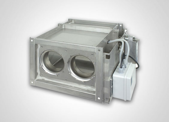
Volume flow controller
VRRM 400
Variable, electronically/pneumatically regulating - rectangular
- Consists of multi-leaf dampers and measuring frame with measuring nozzles
- Pressure measurement via integrated measuring nozzle
- Integrated multi-leaf dampers in standard or airtight version
- All components connected and wired at the factory
- Volume flows and controller set or programmed at the factory
- Special execution: ATEX, painted, stainless steel or with insulation shell
- also available as measuring nozzle without multi-leaf damper (Ref. No.: 248)
Functioning
The electronic and pneumatic volume flow controller we have developed represents a logical extension of our product range. The volume flow controller consists of a multi-leaf damper and a measuring frame. A nozzle compartment with integrated measuring nozzles in integrated in the measuring frame. The measuring nozzles are designed according to the standards DIN EN ISO 5167, so that the differential pressure at the nozzle represents a definite physical quantity, on the basis of which the volume flow can be calculated directly. As a result, it has been possible to dispense with the empirical determination and arrangement of measurement holes for velocity measurement. This differential pressure is transmitted to the measurement sensor of the controller, which adjusts the multi-leaf damper according to the corresponding guidelines via a servomotor. Depending on the make of the controller, the volume flow controller can perform different functions, e.g.: using a command signal to adjust volume flow on a continuous scale between set minimum and maximum values, shutting off, or implementing a “master-slave” servo-control.
Designs
The multi-leaf dampers and the measuring frame are manufactured from galvanised sheet steel. The frame connection profile is canted as a 30 mm high C profile (C30). The blades are designed as torsion-proof hollow sections. The blades are guided via floating bearings. Due to the design of the bearings, only low torques are required for turning the blades. The bearings are airtight. The multi-leaf damper can be supplied as a standard model (no sealing) or as an airtight model. The blades of the airtight model are provided with sealing lips and side seals to obtain a high degree of tightness. The seals of the airtight multi-leaf damper are made of ageing-resistant EPDM or hygienic silicone rubber. The coupling of the blades is effected by aluminium gears. The multi-leaf dampers and the measuring frame are manufactured for each duct cross-section (height and width) in steps of 1 mm as required by the customer. This means that there is no need for adapters, which can be disturbing for the air flow or the look of the duct. The nozzle for volume flow measurement is pressed from galvanised sheet steel. Drill holes are provided in the measuring nozzle for recording pressure. The pressure recording points on the overpressure and negative pressure sides, with four pieces distributed around the circumference, are each connected in a closed circuit, providing a mean value and ensuring that a sufficiently accurate velocity is measured even in case of disturbed velocity profiles. The surface ratio of the nozzle for volume flow measurement (the ratio of the free nozzle cross-section to the pipe cross-section) is designed in such a way that the flow velocity in the nozzle is almost doubled and the differential pressure is therefore multiplied by four. As a result, even relatively low velocities can be recorded. Due to the shape of the measuring nozzle, the inherent resistance remains low in spite of the high differential pressure. The measuring nozzle is crimped into the bulkhead, which, in addition to ensuring firm attachment of the nozzle, increases the rigidity of the measuring box. A corresponding bracket is arranged to provide a sturdy receptacle for the controller, servomotor and pressure sensor.
Controllers and servo motors of different makes and of different types can be mounted on this console. Adjustment can be both electric or pneumatic. Furthermore, the controller can be manufactured from stainless steel throughout (material no. 1.4301 and material no. 1.4571), with a polyurethane coating or with powder coating of the casing in all RAL colours.
Sealing
The frame parts and the mounting parts are designed in such a way that the seal complies with the DIN EN 1507 standard for square components or pr EN 1751 Class C. This securely prevents against leakages and whistling noises. For the operating pressure of up to 1000 Pa and the valid temperature range, in the “closed” position of the multi-leaf damper, tightness can be achieved according to DIN 24194 Part 4 or pr. EN 1751 Class 4.
Measurement principle for velocity recording
The flow velocity is recorded via the measuring nozzle and a differential pressure sensor. Due to the reduced cross-section of the nozzle, the flow rate is increased and the static pressure in the nozzle decreases simultaneously. The measuring holes on the nozzle are positioned in such a way that firstly the total pressure of the flow in the channel, and secondly the static pressure at the most narrow point in the nozzle, are recorded. The difference resulting from the overall pressure in the pipe and the static pressure in the nozzle is a measurement of the flow velocity. This pressure difference (effective pressure) at the nozzle depends quadratically on the flow velocity. The pressure difference is recorded via a differential pressure sensor and transmitted as a sensor signal to the control unit. The sensor signal is transformed within the control unit into a linear actual value (voltage signal). This differential pressure sensor is available in a static and a dynamic version. In the dynamic version, due to the difference in pressure, a small stream of air flows through the pressure sensor and, in a manner similar to a thermal anemometer, the flow velocity is measured and processed further as a signal. In the static version, no air flows through the sensor. Here, the pressure difference is applied directly to a membrane, which is deformed as a result. This deformation is a measure of the pressure difference. The pneumatic controllers operate according to the static principle, except that a pressure signal is transmitted instead of a voltage signal.
Sensitivity of response and accuracy of control
Due to the increased flow velocity in the measuring nozzle and the resulting high differential pressure, the device achieves great accuracy in control and great sensitivity in response. The controller operates from the minimum pressure difference, which is a function of the volume flow, up to the maximum pressure difference of 1000 Pa in a stable control range.
The flow rate variation over the entire pressure range is ±10 %. The flow rates and variations depend however on the make of the controller and must be specified when ordering. The flow velocity should be at least 2 m/s. Due to the measuring nozzle and the manner in which pressure is recorded, the controller is almost insensitive to the flow stream, so that installation is possible where redirection occurs or where junctions are made with short approach sections.
Temperature range
The controller can be employed in its standard version at an ambient temperature of 0° C to +50° C, which takes into account the presence of electronic control components on the device.
Locations suitable for use of the controller
The compact construction guarantees that the air lines can be laid closely adjacent to one another. The volume flow controller can be delivered for any duct cross section, so that there is no need for additional adapters. This makes the installation easier and provides a uniform overall visual scheme when the installation occurs in a visible area. The controller can be used universally, for supply air and exhaust air in high and low pressure plants. Even under unfavourable blower stream conditions, safe functioning is guaranteed with short blower stream lengths. Greater flow rates can be accommodated by parallel switches.
The following types of volume flow controllers are available for selection depending on the location of use and the plant system:
VRR-ME: electronic volume flow controller with analogue command signal
VRR-MP: pneumatic volume flow controller with pneumatic control command
Sound insulation shell
In addition, it is possible to reduce the radiating noise via an insulating shell. The insulation shell consists of a galvanised sheet steel coat and an insulating mat made of mineral wool.
Maintenance
All components are maintenance-free, age-resistant and corrosion-proof under normal conditions. According to DIN EN 12097, accessibility to the piping system and the volume flow controller must be provided for any adjustments or maintenance. In addition the respective manufacturer’s instructions apply to the servo motors and controllers.
Installation and storage at building sites
The controller must be simply installed with the flange profile and independent of the location. A stable duct system is an important prerequisite for proper functioning. This prevents swinging of the channel in the flexible area through quick closing of opening of the locking device. The components should also be stored where they are protected from major soiling through sand or mortar. Care should also be taken during installation that the ducts are free from dirt and loose objects, such as rags, newspapers, packaging materials, etc. The volume flow controllers must not be distorted or deformed. To prevent damage by loose objects or to prevent injury through contact with the multi-leaf damper, it might be reasonable to install a wire grill. The duct should be installed only by specialist staff to avoid obstruction of the cross-section. Please take also note of our document referring to the storage and installation instructions.
Volume flow controller VRRME Ref. No.: 403
Sauter controller, sensor and actuator, ASV205BF132E (5Nm), ASV115CF132E (10 Nm) compact controller
Pressure sensor: static
Volume flow: Vmin 20-80 % and Vmax 30-100% (of V nominal)
Command signal: 0-10V, BACnet
Volume flow controller VRRME Ref. No.: 407
Siemens controller, sensor and actuator GDB 181.1E/3 (5 Nm), GLB 181.1E/3 (10 Nm), compact controller
Pressure sensor: dynamic
Volume flow: Vmin 0-100% and Vmax 20-100% (of V nominal)
Command signal: 0-10V
Volume flow controller VRRME Ref. No.: 410
Belimo controller, sensor and actuator LMV-D3-MP (5 Nm), NMV-D3-MP (10 Nm) compact controller Pressure sensor: dynamic
Volume flow: Vmin 0-100 % (of Vmax) and Vmax 20-100% (of V nominal)
Command signal: 2-10V, MP-Bus
Volume flow controller VRRME Ref. No.: 412
Schischek controller and sensor ExReg-V300-A actuator model ExMax-5.10-CY (5/10 Nm)
Pressure sensor: static
Volume flow: Vmin 0-100 % and Vmax 30-100% (of V nominal)
Command signal: 0-10V
Volume flow controller VRRME Ref. No.: 414
Sauter Controller, sensor and actuator, ASV215BF152E (10Nm), compact controller (3-15sec)
Pressure sensor: static
Volume flow: Vmin 20-80 % and Vmax 30-100% (of V nominal)
Command signal: 0-10V, BACnet
Volume flow controller VRRME Ref. No.: 425
Belimo controller and sensor VRU-D3-BAC, LM24A-VST (5 Nm, 120 s), NM24A-VST (10 Nm, 120 s) or SM24A-VST (20 Nm, 120 s), universal controller
Pressure sensor: dynamic
Volume flow: Vmin 15-100 % and Vmax 20-100% (of V nominal)
Command signal: 2V-10V, BACnet, Modbus, MP-Bus
Volume flow controller VRRME Ref. No.: 426
Belimo controller and sensor VRU-D3-BAC, LMQ24A-VST (4 Nm, 2,4 s) or NMQ24A-VST (8 Nm, 4 s), universal controller
Pressure sensor: dynamic
Volume flow: Vmin 15-100 % and Vmax 20-100% (of V nominal)
Command signal: 2V-10V, BACnet, Modbus, MP-Bus
Volume flow controller VRRME Ref. No.: 427
Belimo controller and sensor VRU-M1-BAC, LM24A-VST (5 Nm, 120 s), NM24A-VST (10 Nm, 120 s) or SM24A-VST (20 Nm, 120 s), universal controller
Pressure sensor: dynamic
Volume flow: Vmin 15-100 % and Vmax 20-100% (of V nominal)
Command signal: 2V-10V, BACnet, Modbus, MP-Bus
Volume flow controller VRRME Ref. No.: 428
Belimo controller and sensor VRU-M1-BAC, up to NW355: LMQ24A-VST (4 Nm, 2,4 s) or from NW400: NMQ24A-VST (8 Nm, 4 s), universal controller
Pressure sensor: dynamic
Volume flow: Vmin 15-100 % and Vmax 20-100% (of V nominal)
Command signal: 2V-10V, BACnet, Modbus, MP-Bus
Volume flow controller VRRMP Ref. No.: 432
Sauter controller model RLP 10, actuator model AK 41 P (3 Nm), actuator model AK 42 P (10 Nm)
Pressure sensor: static
Vmin 20-80% and Vmax 30-90% (of V nominal)
Command signal: 0.2-1 bar
for Windows 7 and 10; standalone programme
Other Languages
Make: Aerotechnik Siegwart, model: VRRM, electronic volume flow controller, rectangular construction, integrated measuring nozzle and mounted console for receiving the actuator and the controller, airtight according to DIN 1507, standard multi-leaf damper or airtight according to DIN EN 1751 Class 4, corrosion-proof, with ageing-resistant seals, with factory-preset settings or programming of the volume flows and the conductance of the controller.
